CAB - Ceiling Diffuser
|
 |
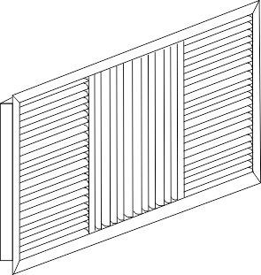 |
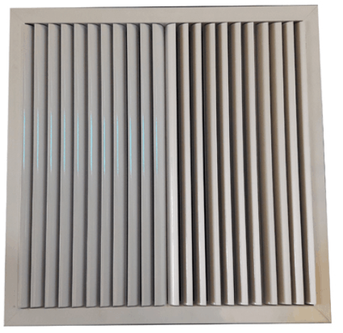
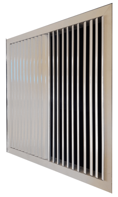
ADJUSTABLE BLADE CEILING DIFFUSER - CAB
|
- Further versatility is added to the diffuser range by way of adjustable blades.
- A similar range of blow patterns as for fixed ceiling diffusers are available.
- Adjustable blades allow ultimate control in the direction of flows.
|
FEATURES
|
- All Aluminium construction offers exceptional quality and performance.
- Light in weight. yet strong and durable.
- Wide range of sizes, both square and rectangular
- Other finishes available upon request.
- Complete selection data to ensure quiet, draft less air distribution.
- Tested and rated in accordance with specifications.
- The performance data which follows permits quick, easy and accurate selection of diffusers.
- Two groups of data are required for selection.
- The first group is that established by the structural and room-use considerations.
- The second group consists of the performance characteristics of the diffusers.
- Consider first the spaces which are to be conditioned and their effects upon outlet selection.
|
AIR FLOW
|
- The performance data which follows permits quick, easy and accurate selection of diffusers.
- Two groups of data are required for selection.
- The first group is that established by the structural and room-use considerations.
- The second group consists of the performance characteristics of the diffusers.
- Consider first the spaces which are to be conditioned and their effects upon outlet selection.
|
| |
 |
NC LEVEL
|
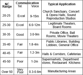
| The permissible sound level in each space may be specified by the owner or the architect, or it may be determined as an engineering design goal. Table 1 contains an abbreviated list of design goals for air-conditioning sound control in common occupancies. |
Pattern Requirement
|
- The pattern requirement is determined by the shape of the space to be conditioned, the number of diffusers in it, and the type and location of lighting fixtures or other devices mounted on the ceiling.
- For example, a two-way opposite 2A, 2B or 2C - might be used in a corridor.
- A larger area can often be divided into squares or rectangles of nearly equal size and, if a diffuser can be located in the centre of each of these areas, patterns 4A or 4B could be used for four-way delivery.
|
Throw Requirement
|
- The required throw is determined from the building plan after the diffuser location has been decided.
- The throw requirement is the distance from the diffuser to the nearest enclosing wall.
- In some cases, the throw requirement will be the distance from the diffuser to the intersection of its air stream with air being delivered from another diffuser.
- For high ceiling applications, the throw requirement may be measured as the horizontal distance described above plus the vertical distance from the diffuser to occupied zone.
- This is usually considered to extend to the 1,5m level in the room.
- Another consideration is diffuser mounting height.
- As air travels from a diffuser, room air is entrained into the supply air stream and the delivery pattern thickens. If the throw requirement is too great, the lower part of the supply air stream can intrude into the occupied zone of the conditioned space.
- To avoid this, diffusers should be located so that the throw requirement is no greater than 1.5 times the diffuser mounting height.
- For example, in a space with a 3.6m ceiling height diffusers should be so located and in such numbers that the required throw of any one diffuser Vi/auld not exceed 5.5m.
- The final consideration is the pressure loss of the diffuser.
|
 |
 |
| |
| Accessories |
PCS |
= |
Punched Counter Sunk Holes |
| |
OBD |
= |
Opposed Blade Damper |
| |
PB |
= |
Plenum Box with spigot |
| |
CP |
= |
Ceiling Plate |
| Frame Options |
30mm |
Standard |
| |
20mm
|
|
|
| |
50mm |
|
|
| |
ON |
= |
Over Neck |
| |
OS |
= |
Over flange |
| |
OP |
= |
Opening or Normal Duct size |
| Finish Options |
NA |
= |
Natural Anodised Aluminium |
| Blade Spacings |
19mm |
Standard |
|
- Ceiling Diffuser available in a choice of Air Distribution Patterns
- Note: H1 is always longer than H2
- All Flow Patterns are given looking at diffuser face
|
|
| |
 |
| |
| Ordering Procedure: Example |
| REF |
QTY |
SIZE (LxH) |
TYPE |
FINISH |
SPECIAL INSTRUCTIONS |
| 1 |
10 |
595 x 595 |
CP |
NA |
TO SUIT 381 X 381 CD-SF |
|
| |
Note:
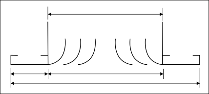
(1) Dimensions given are for over Flange size
(2) Type CAB Core 2A indicates CAB with two way blow |
General Notes on Selections
|
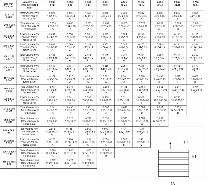
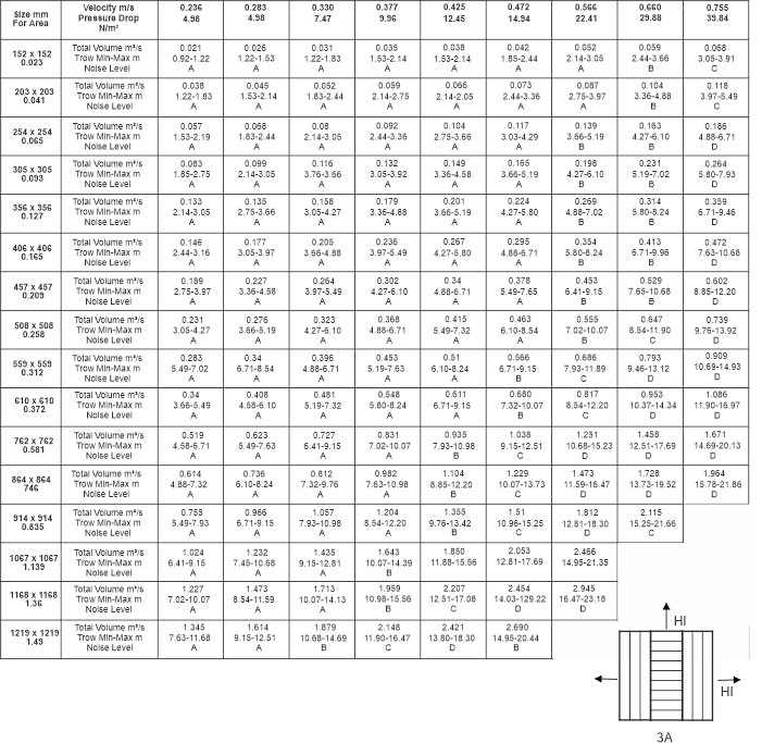
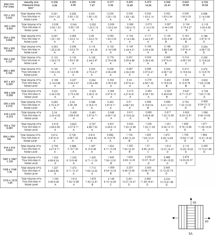
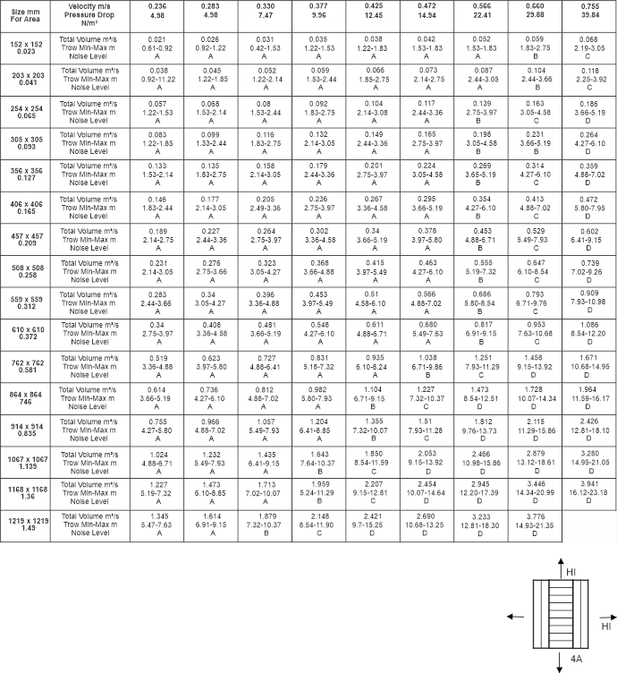
- Total volume means total volume per outlet - m3/sec
- Throw min-max is to a terminal velocity of 0.64 m/s minimum throw and 0.031 m/s at maximum throw.
- Volume H1+H2 means volume per respective side.
- H1 is always larger than H2, except on type 3A where H1=H2.
-
Noise (NC) level.
|
- A = 0 - 30
- B = 31 - 35
- C = 36 - 40
- D = 41 - 45
|
| Selection of curved adjustable blade grille is based upon throw and m3/s requirements. The throw, m3/s and pressure drop apply when the individual blades are adjusted in the manner illustrated below. Other blade settings will provide significantly different throws and air deliveries |
| |
| The m3/s tabulated is the volume delivered by the grille. Balancing of curved blade is accomplished by measuring face velocity. the measured velocity can be correlated to tabulated face velocity and m3/s when the blades adjustment is that as illustrated. |
| |
| The performance of rectangular grilles with areas equal to square grilles, will be the same. |
| |
Selection Data
|
 |
Selection Data
|
 |
Selection Data
|
 |
| |
Selection Data
|
 |
| |


